
1. Taw qhia
The Owon SDS210 is a high-performance 100 MHz, 2-channel digital oscilloscope designed for accurate signal analysis. With a real-time sampling rate of 1 GS/s and a 20M record length, it provides comprehensive waveform capture and analysis capabilities. This manual provides essential information for setting up, operating, and maintaining your SDS210 oscilloscope.
- 100 MHz Bandwidth: Capable of analyzing signals up to 100 MHz.
- 2 Channels: Allows simultaneous analysis of two signals.
- 1 GS/s Real-time SampLing Tus Nqi: Ensures detailed capture of transient events.
- 20M Cov Ntaub Ntawv Ntev: Provides extensive waveform storage for in-depth analysis.
- 7-nti TFT LCD Zaub: Clear visualization of waveforms and measurement data.
- 30 Automatic Measurements: For quick and precise waveform parameter analysis.
- FFT Spectrum Analysis: Advanced signal analysis in the frequency domain.
- USB Connectivity: Supports USB Host and USB Device interfaces for data transfer and PC control.
2. Cov ntaub ntawv kev nyab xeeb
Thov nyeem thiab nkag siab txog txhua cov lus qhia kev nyab xeeb ua ntej siv lub cuab yeej. Yog tsis ua raws li cov lus qhia no yuav ua rau raug mob lossis puas tsuaj rau lub cuab yeej.
- Use only the power adapter supplied with the instrument.
- Do not operate the oscilloscope in wet or damp tej yam kev mob.
- Xyuas kom muaj qhov cua kom zoo los tiv thaiv overheating.
- Do not attempt to repair or modify the instrument yourself. Refer all servicing to qualified personnel.
- Always connect the probe ground lead to earth ground before connecting the probe tip to the circuit under test.
- Saib tag nrho voltage ratings and input limits specified for the oscilloscope and probes.
3. Khoom Tshajview
3.1 Pem Hauv Ntej Vaj Huam Sib Luag
The front panel features the main display, control buttons, and input connectors.

Figure 3.1: Front and Rear Panel Layout with Key Components. This image shows the Power Switch, Function Keys, Button and Knob Control Area, Oscilloscope Signal Input Ports (CH1, CH2), Probe Compensation Output, USB Host Interface, Foldable Handle, Ventilation Holes, Power Socket, and USB Device Interface.
- Lub hwj chim hloov: Turns the oscilloscope on or off.
- Function Keys: Access various menus and settings.
- Button and Knob Control Area: Includes controls for vertical, horizontal, trigger, and menu navigation.
- Oscilloscope Signal Input Port (CH1, CH2): BNC connectors for connecting probes to input signals.
- Probe Compensation Output: 5V/1kHz signal output for probe calibration.
- USB Host Interface: For connecting USB storage devices to save or retrieve data.
3.2 Lub Vaj Huam Sib Luag
The rear panel includes the power input and additional connectivity options.
- Foldable kov: Rau yooj yim portability.
- Qhov Ventilation Holes: Essential for heat dissipation.
- Lub qhov fais fab: Txuas rau AC fais fab mov.
- USB Device Interface: Used to connect the oscilloscope to a PC for data transmission and remote control.
4. Teeb tsa
4.1 Unpacking
Carefully remove the oscilloscope and all accessories from the packaging. Verify that all components listed in the packing list are present and undamaged. Keep the original packaging for future transport or storage.
4.2 Kev sib txuas fais fab
- Connect the provided power cord to the power socket on the rear panel of the oscilloscope.
- Txuas rau lwm qhov kawg ntawm txoj hlua hluav taws xob mus rau hauv lub qhov hluav taws xob AC hauv av.
4.3 Kev sojntsuam txuas
Connect the oscilloscope probes to the CH1 and CH2 BNC input ports on the front panel. Ensure the connectors are securely twisted into place.
4.4 Kev Tshawb Fawb Kev Ua Haujlwm
Before taking measurements, it is crucial to compensate your probes to ensure accurate readings. This process matches the probe's capacitance to the oscilloscope's input capacitance.
- Set the probe attenuation to 10X.
- Connect the probe tip to the Probe Compensation Output terminal (5V/1kHz) on the front panel.
- Connect the probe's ground clip to the ground terminal next to the compensation output.
- Press the AUTO button to automatically adjust the waveform.
- Observe the square wave displayed on the screen. Adjust the trimmer capacitor on the probe until the square wave corners are flat, without overshoot or undershoot.
4.5 PC Connection (USB Device Interface)
To connect the oscilloscope to a computer for remote control or data transfer:
- Use a standard USB cable to connect the USB Device Interface port on the rear panel of the oscilloscope to a USB port on your computer.
- Install the necessary drivers and software provided by OWON for your specific operating system.
5. Kev ua haujlwm yooj yim
5.1 Hwj chim Rau/Tawm
Press the Power Switch on the front panel to turn the oscilloscope on. Press it again to turn it off.
5.2 Zaub Tshajview
The SDS210 features a 7-inch TFT LCD display that provides a clear view of waveforms, measurement results, and instrument settings.
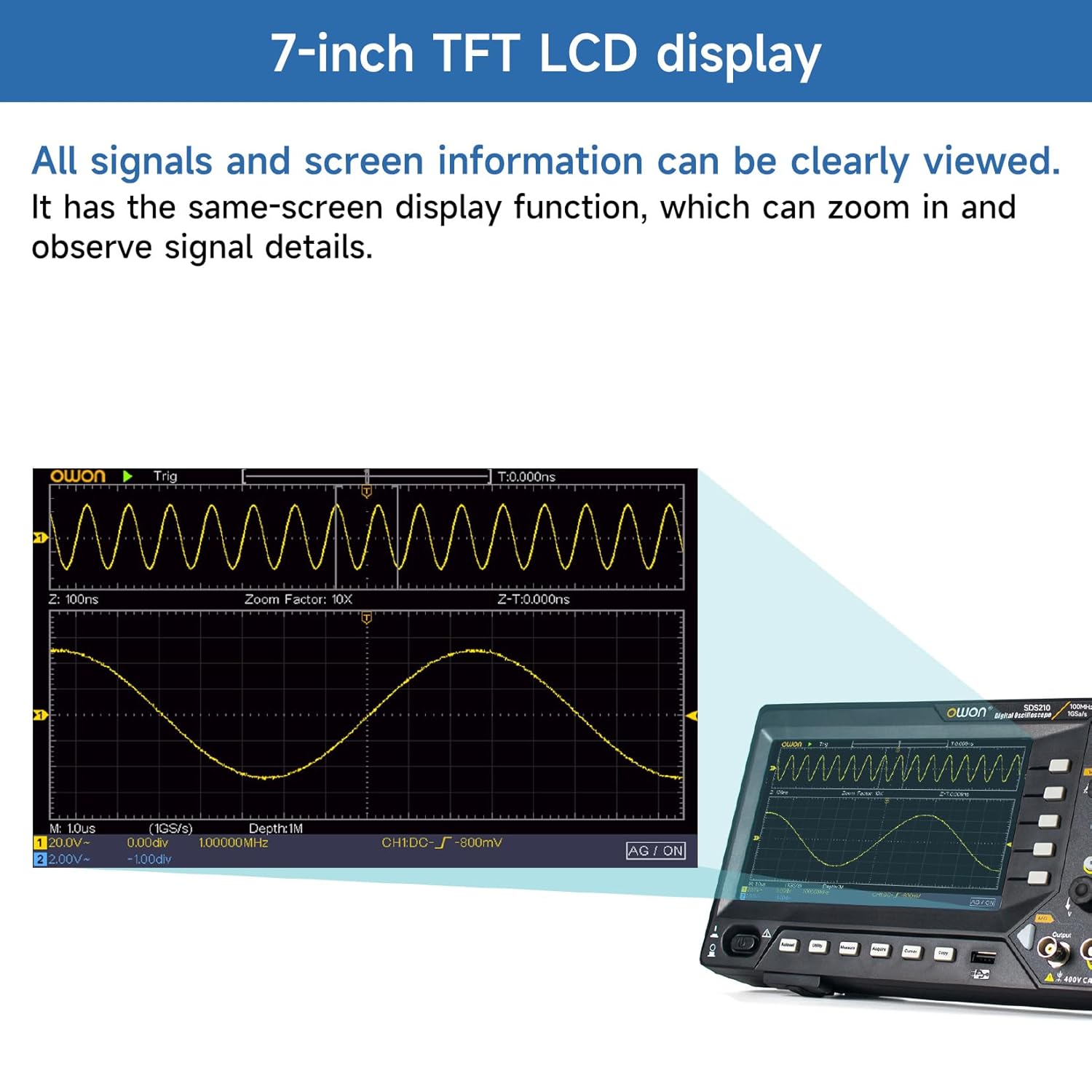
Figure 5.2: 7-inch TFT LCD Display. All signals and screen information can be clearly viewed. It has a same-screen display function, which can zoom in and observe signal details.
5.3 Basic Waveform Zaub
After connecting a signal to an input channel, press the AUTO button. The oscilloscope will automatically adjust the vertical, horizontal, and trigger settings to display a stable waveform.
5.4 Vertical Controls
The vertical controls adjust the amplitude and position of the waveform.
- Vertical Position Knob: Moves the waveform up or down on the screen.
- Vertical Scale Knob (V/div): Adjusts the vertical sensitivity (volts per division).
- Cov nyees khawm CH1/CH2: Selects the active channel for adjustments or turns channels on/off.
5.5 Kab rov tav tswj
The horizontal controls adjust the time base and position of the waveform.
- Horizontal Position Knob: Moves the waveform left or right on the screen.
- Horizontal Scale Knob (s/div): Adjusts the time base (seconds per division).
5.6 Kev Tswj Xyuas Kev Ua Haujlwm
The trigger controls stabilize repetitive waveforms and capture single-shot events.
- Trigger Level Knob: Teem lub voltage level at which the trigger occurs.
- Trigger Menu Button: Accesses trigger settings such as edge, pulse, video, and slope.
- Force Button: Forces a trigger event.
6. Advanced Features
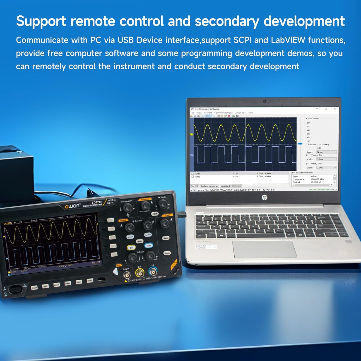
Figure 6.0: Advanced Measurement and Analysis Modes. This image illustrates the 6-digit High-precision Frequency counter, FFT Spectrum Analysis, Cursor Measurements, 30 Automatic Waveform Measurements, Save/Recall functions, and X-Y mode.
6.1 Kev ntsuas tsis siv neeg
The SDS210 offers 30 types of automatic waveform measurements for quick and accurate analysis of signal parameters. Press the MEASURE button to access the automatic measurement menu.
- Common measurements include Period, Frequency, Mean, Peak-PK, RMS, Max, Min, Top, Base, Amplitude, Overshoot, Preshoot, Rise Time, Fall Time, Pulse Width, Delay, Duty Cycle, and more.
6.2 FFT Spectrum Analysis
Perform Fast Fourier Transform (FFT) to analyze signals in the frequency domain. This is useful for identifying harmonics, distortion, and noise components.
- Press the MATH button.
- Select 'FFT' from the Math menu.
- Adjust the FFT settings such as source, window type, and display format.
6.3 Cursor Measurements
Use cursors to manually measure specific points on a waveform. Press the CURSOR button to activate and control the cursors.
- Voltage Cursors: Ntsuas voltage differences (ΔV).
- Time Cursors: Measure time differences (ΔT).
6.4 Save/Recall Waveforms
The oscilloscope allows you to save and recall waveform data and instrument settings to internal memory or a connected USB drive.
- Press the SAVE button to access saving options.
- Select the desired save type (waveform, setup, image) and destination (internal, USB).
6.5 X-Y Mode
X-Y mode is used to display the relationship between two signals, often for phase comparison or Lissajous figures.
- Ensure signals are connected to CH1 and CH2.
- Access the Display menu and select X-Y mode.
6.6 Remote Control and Software
The SDS210 supports remote control and secondary development via its USB Device Interface, utilizing SCPI (Standard Commands for Programmable Instruments) and LabVIEW functions. Free computer software and programming development demos are available to facilitate remote instrument control.

Figure 6.6: Remote Control and Secondary Development. Communicate with a PC via the USB Device interface, supporting SCPI and LabVIEW functions. Free computer software and programming development demos are provided for remote control and secondary development.
7. Kev tu
7.1 Kev ntxuav
Yuav ntxuav cov cuab yeej, siv daim ntaub mos mos dampened with a mild detergent. Do not use abrasive cleaners or solvents that could damage the casing or display. Ensure the instrument is powered off and disconnected from the power source before cleaning.
7.2 Cia khoom
When not in use for extended periods, store the oscilloscope in a dry, dust-free environment. Use the original packaging for protection during storage or transport.
7.3 Qhov cua
The oscilloscope is equipped with ventilation holes on the rear panel to prevent overheating. Ensure these holes are not obstructed during operation to allow for proper airflow.
8. Kev daws teeb meem
Tshooj lus no muab kev daws teeb meem rau cov teeb meem uas koj yuav ntsib.
- Tsis muaj zog: Check the power cord connection and the power outlet. Ensure the power switch is in the 'ON' position.
- Tsis Muaj Waveform Zaub: Verify that a signal is connected to the input channel. Check probe connections and ensure the channel is enabled. Press the AUTO button to automatically adjust settings.
- Waveform tsis ruaj khov: Adjust the trigger level and trigger settings (e.g., edge, slope). Ensure the trigger source is correctly selected.
- Kev ntsuas tsis raug: Perform probe compensation as described in Section 4.4. Check the probe attenuation setting on both the probe and the oscilloscope.
- Cov teeb meem ntawm USB txuas: Ensure the correct drivers are installed on your PC. Try a different USB cable or port.
If the problem persists, contact OWON customer support or your local distributor for assistance.
9. Cov lus qhia tshwj xeeb
The following table details the technical specifications for the Owon SDS210 Digital Oscilloscope.

Figure 9.0: Owon SDS210 Series Oscilloscope Specifications. This table provides detailed specifications including Bandwidth, Sample Rate, Acquisition Mode, Input Coupling, Input Impedance, Probe Attenuation Factor, Record Length, Horizontal Scale, Vertical Sensitivity, Automatic Measurement types, Waveform Math functions, Waveform Storage, Lissajous Figures, Trigger Type, Communication Interface, Frequency Counter, and Waveform Generator Specifications (for SDS210S, SDS215S, SDS220S models).
| Feature | Specification (SDS210) |
|---|---|
| Chaw tsim tshuaj paus | OWON |
| Qauv nab npawb | SDS210-OW |
| Bandwidth | 100 MHz |
| Cov channel | 2 CH |
| Samptus Nqi | 1 GS/s |
| Cov ntaub ntawv ntev | 20m ib |
| Tau txais hom | Normal, Peak detect, Averaging |
| Input Coupling | DC, AC, hauv av |
| Input Impedance | 1MΩ±2%, in parallel with 20 pF±5 pF |
| Kev sojntsuam Attenuation Factor | 1 X, 10X, 100X, 1000X |
| Kab rov tav nplai (s/div) | 2 ns/div-1000 s/div, step by 1-2-5 |
| Vertical Sensitivity | 2 mV/div-10 V/div |
| Tsis Siv Neeg Ntsuas Kev Ntsuas | Lub Sijhawm, Zaus, Mean, PK-PK, RMS, Max, Min, Sab saum toj, Base, Amplitude, Overshoot, Preshoot, Rise Time, Fall Time, +PulseWidth, -PulseWidth, +Duty Cycle, -Duty Cycle, Delay A→B↑, Delay A→B↓, Cycle RMS, Cursor RMS, Screen Duty, Phase, +PulseCount, -PulseCount, RiseEdgeCnt, FallEdgeCnt, Area, and Cycle Area. |
| Waveform Math | +, -, ×, ÷, FFT |
| Waveform Cia | 16 waveforms |
| Lissajous's Bandwidth | full bandwidth |
| Lissajous's Figure Phase Difference | ± 3 degrees |
| Lub hom phiaj | Edge, Video |
| Kev sib txuas lus Interface | USB Host and Device |
| Zaus Counter | muaj |
| Khoom Dimensions (L x W x H) | 29.97 x 7.01 x 15.24 cm (11.8 x 2.76 x 6 nti) |
| Khoom hnyav | 1.1 kg (38.8 ooj) |
10. Warranty thiab Support
10.1 Warranty Information
For detailed warranty information, please refer to the warranty card included with your product or contact your authorized OWON dealer or the manufacturer directly. Warranty terms and conditions may vary by region and retailer.
10.2 Kev Pabcuam Cov Neeg Siv Khoom
If you require technical assistance, have questions about your product, or need to report an issue, please contact OWON customer support. Contact information can typically be found on the manufacturer's official webqhov chaw lossis los ntawm cov ntaub ntawv ntawm koj cov khoom.